December 14, 2021

Pulse Oximeter Repair Solution | Pulse Oximeter Assembly | What inside Oximeter?

Pulse Oximeter

A pulse oximeter is a device that is usually placed on the fingertip. It uses light rays to estimate the oxygen saturation and pulse rate of the blood. Oxygen saturation provides information about the amount of oxygen in the blood. A pulse oximeter can estimate the amount of oxygen in the blood without taking a blood sample.

Pulse Oximeter Repair Solution

If your pulse oximeter is not working properly, try inserting your finger again and keeping your finger pressed on the device, keeping your finger still while reading. Take another reading to get the correct results. See below for details on how to properly insert your finger into the pulse oximeter.

What to do if the oximeter is not working?

  • If your pulse oximeter is not displayed then check Batteries are placed in a proper manner like polarities.
  • Check the pulse oximeter probes and SPO2 sensor cables.
  • In most cases SMD on-off button failure because of frequently used in that case you need to change it.
  • Oxygen levels fluctuate and home pulse ox monitors may lose connection or momentarily read incorrectly.

Pulse Oximeter Repair Solution | Pulse Oximeter Assembly | What inside Oximeter?

Which Sensor is used in Pulse Oximeter?

All pulse oximeters use red and infrared light to measure SpO2 levels. Nonin PureLight sensor technology uses high-quality LEDs and a calibrated receptor to eliminate interference from secondary frequencies.

December 12, 2021

Solenoid Switch Working Principle | Types of Solenoid Switch and its Applications Price

What is a Solenoid Switch

The Solenoid Switch is a type of switch that functions using the principle of electromagnetic induction. When current flows through a coil of wire, it creates a magnetic field within the coil. When the current is turned off, the magnetic field created by the current continues to exist. This causes the solenoid to continue to respond to the signals being sent by the circuit board, producing a series of clicks as current flows through the coil.

A solenoid Switch is an Electrical Switch is used in high power circuits for switching purposes by using a small control signal. The high current circuits are starter motor circuits operated by a small current switch, this switch is mainly operated by extensive logic circuits and it is economically integrated chips and small electronic components. In this article, I discussed Solenoid Switch and its applications.

Solenoid Switch

Solenoid Switch Definition

An electrical switch that is widely used in high current circuits like motor starter circuits comes into action with help of small power switching is called a Solenoid Switch. This switch turns ON a durable switch to connect the battery of a vehicle to the motor’s starter. Once the ignition key is activated then a solenoid switch connects the drive pinion starter. The main features of solenoid switches are high performance, reliability, and durability.

Purpose of Solenoid Switch

A solenoid switch is used to control high-power circuits with the help of small electrical control signals to activate the switch. It also allows the high-power conversion device to be limited to a remote area. These switches are commonly used in automotive engine starting systems.

The Solenoid Switch allows users to turn off the light at a specific location. This is useful for turning off a light in a specific room, or for turning off a light when a person is not present. The light remains on for a short amount of time after the person has left the room, and then turns off on its own.

Solenoid Switch Price

Vital All-Terrain (2) 12V Solenoid Switch 1013609 for 1984-Up Club Car DS, Precedent Gas Golf Cart

solnoid switch price

Corslet Soldering Tool Kit


December 6, 2021

DC to DC converter +12V to +/-20V Circuit | Applications of DC to DC Converter

DC to DC converter

The DC to DC power supply converts the DC power coming from your wall outlet into a higher voltage that can be used to power electronic devices. The power output of a DC to DC converter is a constant voltage, meaning the voltage is the same regardless of how much current is being drawn. This prevents the power converter from being a risk for overloading, which is important when powering devices that can draw a large amount of current, like computers and electric drills. DC to DC converters usually has multiple output voltages, allowing you to choose the voltage that is best for your application.

DC to DC Converter circuit used to be a converted voltage DC to DC with different concepts. DC to DC converter circuit +12 V to + /-20V is working to change the battery voltage from 12V DC to 20V DC voltage


DC-To-DC-Converter

DC to DC converter +12V to +/-20V Circuit


3000W Stereo Power Amplifier Circuit Diagram using with Transistors

3000W Stereo Power Amplifier

This power amplifier circuit uses a transistor amplifier from the front, signal splitter, driver, and power amplifier. The current consumption required is quite a large power amplifier that is 15-20 A 1500W power amplifier circuits for this. The supply voltage needed by the power of this amplifier is the optimal working order symmetrical 130VDC.


3000W Stereo Power Amplifier Circuit

3000W Stereo Power Amplifier Circuit

The power amplifier circuit has a power output of up to 1500W RMS power amplifier circuit is often used to power sound systems for outdoor, power amplifier 1500W is equipped to control a DC Offset function to set the power amplifier is turned on at the moment and with no input signal then the output should be 0VDC. They are also equipped with a flow regulator to the power amplifier bias.

In the above series of power amplifiers, 1500W is equipped to control a DC Offset function to set the power amplifier is turned on at the moment and with no input signal then the output should be 0V DC. Then also equipped with a flow regulator to the power amplifier bias. The final part of this power amplifier requires adequate cooling to absorb the heat generated. The power amplifier is not equipped with a speaker protector, therefore it is necessary to diapason protector on the speaker output so that when the power amplifier is not the case turned on the beat to the speaker can damage the speaker.

Gemini GPA-3500 3000W Professional DJ Power Amplifier


Advantages of high power amplifiers

Strong Bass Boost, not Saggy

Secondary comfortable bias voltage (can be AC (transformer) / DC (adapter))

Highly Efficient Rail – Stack Layout

Oversized Heatsink & Output Coil (not easy saturation)

Pulse Resolution Adjust Enable

December 1, 2021

Free Fire Redeem Code For December 23, 2021 Codes For Free Rewards, Free Fire New Update

Free Fire Redeem Code for Dec 23, 2021: Reward Code OB30 update

Free Fire is an online battlefield gaming platform that offers many lucrative and exciting gaming experiences. It is very popular among young people all over the world. To improve the experience, various attractive weapons, loot boxes, currencies, etc. are introduced. These unique items can be obtained using real money or redemption codes/reward codes. check here circuits99.com

Free Fire Redeem Code

Garena Free Fire Redeem codes are updated daily by game developers. These FF redemption codes can be used by players to add features and get a better gaming experience. These codes can be used for free within a specified time frame.

How to redeem Free Fire redeem codes?

  • Go to the official Free Fire redeem code redemption website.
  • Log in using Facebook, Google, Twitter, or Apple IDs.
  • Copy and paste any of the redeem codes mentioned above into the text box and click on confirm button to continue.
  • Provide confirmation on the box that opens for cross-checking the request by clicking on OK.
  • Check the game mail section, which is embedded, for rewards after successfully redeeming the codes.
  • Once the redemption is done, it might take as long as 24 hours for the rewards to show up in a player’s in-game mail.

Garena Free Fire Redeem codes for December 23, 2021

  • DDHSG83BDGKXUYT > Free Pet
  • FFGT9HDWMPOKH > Justice Fighter and Vandals Rebellion Weapons Loot Crate
  • FFGLZGFDDQO > Free Fire Diamonds
  • NH7VCMWKLCSVW > Titian mark gun skins
  • MJTFA67VCFMHP19 > 80,000 diamond codes
  • 3AAW19NGDDF4UB > free dj alok character
  • 2LKVQWPO6HS9UY > Diamond Royale Voucher
  • BH77AHAY94BS3NW > Elite Pass and Free Top Up
  • W3XCLDGA7BAAQE > Paloma Character
  • 3GHSHBVJ6A9Z > Outfit

Garena Free Fire redeem codes for December 2021

  • F1QS DFGY 657U > Premium Bundles
  • F2QA ZXCV BHNM > Sneaky Clown Weapon Loot Crate
  • F2QA SFGY T5GH > Free 299 Diamonds Bundle
  • F34R FGBN MKLO > Free Diamonds Voucher
  • FFGY BGFD APQO> Free Fire Diamonds
  • F8IK NBVF R55T > Dreki Pet Free Fire Code
  • F9IK MNBV CDER > Head Hunting Parachute

Additional Garena Free Fire Latest Redeem Codes 

  • F876 T5RE SWQ2
  • F234 56YH GDFG
  • FBVC SDFG HJKL
  • F987 6TRF DSE4
  • FJKL O098 7YTF
  • FXZA Q234 R5TY
  • FE45 T6YU JNBV

Free Fire India Redeem Code

  • FFICJGW9NKYT (India server)
  • DDFRTY1616POUYT> Free Pet
  • FFGYBGFDAPQO> Free Fire Diamonds
  • MJTFAER8UOP16> 80,000 diamond codes
  • SDAWR88YO16UB> free dj alok character
  • BHPOU81616NHDF> Elite Pass and Free Top Up
  • ADERT8BHKPOU> Outfit
  • NHKJU88TREQW> Titian mark gun skins
  • MHOP8YTRZACD> Paloma Character
  • FFGTYUO16POKH> Justice Fighter and Vandals Rebellion Weapons Loot Crate
  • BBHUQWPO1616UY> Diamond Royale Voucher

FF Redeem Codes and Free Fire Rewards

Redeem CodeRewards
R9UVPEYJOXZX3x Weapon Royale Voucher
FFGYBGFDAPQOFree Fire diamonds
BBHUQWPO1111UYDiamond Royale Voucher
DDFRTY1111POUYTFree Pet
FFGTYUO11POKHJustin Fighter and Vandals Rebellions Loot Crate
FFMCLJESSCR72x MP40 New Year Weapon Loot Crate
FFMC5GZ8S3JC2x Flaming Red Weapon Loot Crate
XUW3FNK7AV8N2x Custom Room Cards
FFMC6UR5ZNJQOld Fashioned Weapon Loot Crate
XLMMVSBNV6YC2x Winterlands Weapon Loot Crate
FFMC2SJLKXSB2x Scorching Sands Weapon Loot Crate
LH3DHG87XU5U1x Diamond Royale Voucher
1x Weapon Royale Voucher
PACJJTUA29UU1x Diamond Royale Voucher

Garena FF Redeem Codes Today

  • FJKI 8U7Y 6TRF
  • FIH8 FS76 F5TR
  • FBJK I9Z7 F65R
  • FFGB VIXS AI24
  • FBNJ I87Y 6TGH
  • FTRF VBHJ FI87
  • FSER 5T6Y 7U8I
  • FBHJ UYTR FICV
  • XM5L93V38NGX
  • 732OIF59VMZ1
  • NV944T60B9GK
  • FFA0ES11YL2D
  • FFX60C2IIVYU
  • FFXVGG8NU4YB
  • FFE4E0DIKX2D
  • FF22NYW94A00
  • FF5XZSZM6LEF
  • FFTQT5IRMCNX
  • FF7WSM0CN44Z
  • FFA9UVHX4H7D
  • XBY47AFNNUD6
  • MCPKE62KW5MX
  • FF10617KGUF9
  • 87JR8K8AKP64
  • 9BYDPUM5WK6Z
  • JIMYLVT46V2Z
  • 8JKNXUB96C9P
  • 8FEUQJXPDKA7
  • MV9CQ27LQJOL
  • 3OVTN5443GFQ
  • PUSR0KI57R77
  • FFXVGG8NU4YB
  • FFE4E0DIKX2D
  • ERTYHJNBVCDS
  • F9IUJHGVCDSE
  • F7UIJHBGFDFR
  • FXCVBNMKDSXC
  • F0KMJNBVCXSD
  • FF22NYW94A00
  • FF5XZSZM6LEF
  • FFTQT5IRMCNX
  • FF7WSM0CN44Z
  • 9SR8E1WJEHF6
  • UNGQ36T7BHZJ
  • E71XWBFU6RO7
  • QNUH4C1G5QBQ
  • ZFUJWLLPG4P4

FF Reward Codes Important Sites

Check Garena Fire Free Redeem Codes Todayhttps://reward.ff.garena.com/en
Garena Free Fire- Rampage Official Websitehttps://ff.garena.com/index/en/

November 20, 2021

What is a Power Amplifier? | Types of Power Amplifiers, Amplifier Price

What is a Power Amplifier?

In this article, we will discover an interesting subject in the field of electronics the power amplifier. They are used in Audio applications, Radio communications, Medical equipment like MRI, headphones, RF transmitters, and more. Thus, we will learn what the power amplifier is, what are the different types of power amplifiers, the classes of power amplifiers, and also some applications.

Power Amplifier

Power Amplifiers are basically used to increase the power level of the input signal. A power amplifier, also known as a large signal amplifier, needs to have a high input signal voltage to get high power at the output.

Types of Power Amplifiers

Power Amplifiers are divided into the following three types they are Depending on the type of output device connected

  • Audio Power Amplifiers
  • RF Power Amplifiers
  • DC Power Amplifiers

Audio Power Amplifiers

An audio power amplifier (or power amplifier) is an electronic amplifier that amplifies low-power electronic audio signals such as a signal from a radio receiver or an electric guitar microphone to power speakers or earphones.

RF Power Amplifiers

Radio Frequency power amplifier (RF power amplifier) is a type of electronic amplifier that converts a low-power radio frequency signal into a high power signal. Typically, RF power amplifiers drive the transmitter antenna. Design goals often include gain, output power, bandwidth, power efficiency, low linear signal compression at rated output, matching input and output impedance, and heat dissipation…

DC Power Amplifiers

A Direct-Coupled Power amplifier, or DC Power Amplifier, is a type of amplifier that combines the output of one phase of the amplifier with the input of the next phase to enable zero frequency signals, also known as direct current. , Go from the entrance to exit.

Applications of Power Amplifiers

  • Power amplifiers are most widely used in broadcast transmitters,
  • Used in wireless transmitters and high audio systems.
  • Bipolar transistors are used for these applications.
  • Power output and efficiency are mostly considered in power amplification.
  • Industrial Applications like Switching type power amplifiers are used for controlling the industrial actuator systems like Servo motors and DC motors.
  • Audio power amplifiers are used in almost all consumer electronic devices ranging from microwave ovens, headphone drivers, televisions, and Home theatre systems.

November 17, 2021

SCR Applications | What is SCR (Silicon Controlled Rectifier)

What is SCR?

The term SCR stands for silicon-controlled rectifier which is one of the most important members of the thyristor family. A silicon-controlled rectifier or semiconductor-controlled rectifier is a four-layer solid-state current-controlling device.

SCR Applications

SCR Symbol

The silicon-controlled rectifier is a one-way current control device. Like a simple p-n junction diode, it allows current to flow in one direction only and prevents current from flowing in another direction. A common p-n junction diode is made of two semiconductor layers, P-type and N-type. However, an SCR diode is made of 4 semiconductor layers with alternating P and N-type materials.

SCR Applications

Below are some important applications of Silicon Controlled Rectifier (SCR)

  • The silicon-controlled rectifier (SCR) is used in AC voltage stabilizers.
  • The silicon-controlled rectifier (SCR) is used as a switch.
  • It is used in choppers.
  • The silicon-controlled rectifier (SCR) is used in inverters.
  • The silicon-controlled rectifier (SCR) is used for power control.
  • It is used for DC circuit breakers.
  • A silicon control rectifier (SCR) is used in a battery charger.
  • It is used to Adjust the light dimmer.
  • It is used to control motors speed.
  • The SCR is used in the pulse circuits.
  • It is used for AC power control with a solid relay.

SCR Full Form

SCR full form – silicon-controlled rectifier

SCR full form in Electronics

Silicon Controlled Rectifier or Semiconductor Controlled Rectifier

SCR full form in Electrical

Silicon Controlled Rectifier or just Thyristor

Types of Thyristors

  • Silicon controlled thyristor or SCRs
  • Gate turn off thyristors or GTOs
  • Emitter turn off thyristors or ETOs
  • Reverse conducting thyristors or RCTs
  • Bidirectional Triode Thyristors or TRIACs
  • MOS turn off thyristors or MTOs
  • Bidirectional phase controlled thyristors or BCTs
  • Fast switching thyristors or SCRs
  • Light-activated silicon controlled rectifiers or LASCRs
  • FET controlled thyristors or FET-CTHs
  • Integrated gate commutated Thyristors or IGCTs

Silicon controlled thyristor or SCRs

Silicon-controlled rectifiers or SCRs are used primarily in power applications. An SCR is a semiconductor device that conducts electric current when activated, and blocks current when deactivated. The on and off states of an SCR are controlled by the presence or absence of a controlled current through its gate, which is a control wire in the semiconductor. The majority of SCRs use a thyristor as a control element, though some use an SCR alone.

Gate turn off thyristors or GTOs

Gate turn-off thyristors or GTOs are used to control the flow of a gate device. They are usually controlled by a digital signal which is sent to the gate turn-on thyristors or GTOs. The thyristors or GTOs act like a switch, turning the flow of current off when the signal is high and on when the signal is low. The signal can be set up to turn on multiple thyristors or GTOs in parallel to control the flow of a larger current.

November 14, 2021

What is Cricut Machine? & Best Cricut Machines in 2021

Cricut Machine

If you are new to the Cricut machine, you may be surprised what a Cricut machine is? and what does do it exactly? Do we need this machine?

What Is Cricut Machine

Cricut machine images

Actually, a Cricut is a digital die-cutting machine we can able to cut different materials by using this Cricut machine for you to use in an Abundant of craft projects. We can cut materials like paper and vinyl by using the correct cutting blades. Some Cricut Machines also cut fabrics, leather, balsa, and cork.

Best Cricut Machines in 2021

The Best Cricut machine is a great investment for crafters to make desired to cut on paper and vinyl material. In this article, you will get info on many different types of Cricut machines rated by hundreds of users.

The best Cricut Machines are,

Cricut Maker

This best overall product and it comes with a bunch of features that are noticeably absent in other Cricut machines.

  • Cuts 300+ materials
  • 10X more power than other models
  • Works with 12+ tools for pro-level scoring, engraving, debossing & other effects
  • Comes with hundreds of digital sewing patterns
  • Powerful blades
  • Has Bluetooth connectivity
  • Automatically detects whether you are using the right blade or not
  • Produces high-quality cuts very quickly

Cricut Explore Air 2

This feature makes the Explore Air 2 the best Cricut machine for vinyl. Using its embedded Bluetooth technology allows for wireless cutting; only one of its awesome features.

  • Cuts 100+ types of material
  • 2X faster cutting and writing
  • Comes with embedded Bluetooth
  • Comes with free access to Cricut’s design software
  • Ample storage space
  • Precise cutting
  • Offers good value for money

Cricut Joy

It is the most compact cutting machine so far and Cricut Joy allows you to customize your designs using a wide variety of line weights and pen types. The write, doodle, and draw functions can achieve any shapes, patterns, letters, numbers, objects, and more.

  • Super compact, lightweight only 3.9 lbs
  • Cuts 50+ types of material
  • Cuts up to 20-ft long and 4-in wide
  • Card mat for quick custom card
  • Fast and quiet operation
  • Easy to set up, super portable, and easy to travel with
  • 50 free online projects for inspiration

Cricut Easy Press 2

This Cricut Press 2 machine provides both actions like Cricut machine and immersive iron on the machine also,

  • Best for iron-on vinyl
  • Allows for precise temperature control
  • Provides results in at most 60 seconds
  • Light and portable
  • Light and portable
  • Compatible with most heat-transfer vinyl brands
  • Comes in a variety of sizes
  • Gives professional results

Cricut Mug Press

It is a single-button, foolproof mug pressing machine that automates the entire process you don’t have to worry about any setting, Imagine a fancy device that huffs and puffs and transforms your mugs into gorgeous looking personalized drinking companions.

  • Best for printing on 11-16 oz mugs
  • Optimized for Infusible Ink products
  • Safety-conscious and compact design
  • Easy to set up and use
  • Easy setup and operation
  • Infusible Ink technology ensures the designs are permanent
  • The foolproof mechanism that can be mastered by anyone
  • Quick sublimation process
  • No heat or pressure settings required

These are the best cutting machines from Cricut Machines.

Also Read: 5.1 Prologic Board price | B-Tech Audio DTS Boards with Remote Kit With Display

November 7, 2021

2000W Power Amplifier Circuit Diagram | Class H Amplifier Circuit Diagram

2000W Power Amplifier

2000W  Power Amplifier Circuit Diagram is the article on circuits99.com explaining 2000W Class AB Power Amplifier Circuit Diagram This is the circuit diagram of 2000W class AB power amplifier.

2000W-Power-Amplifier


2000W Class AB Power Amplifier Circuit Diagram

The circuit diagram of the 2000W class AB power amplifier uses 7 pairs of MJ15003 and MJ15004 transistors for the final amplification block. The circuit operated with 90V DC symmetrical (dual polarity) power supply circuit. The transistors must be mounted on the heatsink to prevent overheating, maintain the transistor’s work in maximum performance.

Also Read: 18W AUDIO POWER AMPLIFIER CIRCUIT USING TRANSISTORS

2000W Power Amplifier Specifications:

  • Max. Output Peak Power: 2000 Watt Peak @ 2? Ohms Loudspeaker
  • Max. RMS Output RMS Power: 1000 Watt RMS @ 2? Ohms Loudspeaker
  • Max. Bridged RMS Output Power: 2000 Watt RMS @ 4? Ohms Loudspeaker
  • RMS Output Magnitude: 44.7v RMS
  • Peak Output Magnitude: 65v Peak
  • Freq. Response: 20Hz ~ 20KHz
  • Max. Output Gain: 40dB
  • Input: 100mV Peak
  • DC Power Supply: 90v DC (Dual Supply)

2000 watts power amplifier circuit Working:

  1. This is the circuit diagram of the 2000W class AB power amplifier that uses 7 pairs of MJ15003 and MJ15004 transistors for the final amplification block.
  2. The circuit operated with 90V DC symmetrical (dual polarity) power supply circuit.
  3. The transistors must be mounted on a heatsink to prevent overheating, maintain the transistors’ work in maximum performance.

2000 watt Amplifier Price

Ahuja 2000 watt Amplifier Price

Related:

SUBWOOFER AMPLIFIER CIRCUIT BY IC TDA2030

5.1 Prologic Board price | B-Tech Audio DTS Boards

2000W Class H Amplifier Circuit Diagram

November 6, 2021

Fuse Resistor Applications | Fuse Resistor Color Code

What is Fuse Resistor?

Fuse Resistors are used to protect circuits from overheating, voltage spikes, and lightning. They are typically made from a semiconductor material such as a resistive wire or a metal strip and are used in series with other components to reduce the risk of short-circuiting. Fuse Resistors have a resistance that decreases as they warm up. When they reach a certain temperature, the Fuse Resistors turn off, preventing the current from flowing through them.

Wirewound Fuse Resistors

Wirewound Fuse Resistors

Wirewound Fuse Resistor

Wirewound Fuse Resistors are designed to function as a normal resistor under normal conditions and as a fuse at high loads. In the WWF series, resistors up to 5W are color-coded with a resistance value of 3 bands as well as a tolerance band. An additional white stripe indicates that the resistor is fusible. For resistors 6W and above, the value is printed on the resistor.

Which resistor is used for the fuse?

Fusible Film Resistors are used in a variety of low power and low surge applications. These include low-level fire safety, surveillance and maintenance, high-end audio/video systems, environmental management systems and controls, and laser printers.

Applications of Fuse Resistor

  1. Overload or surge production
  2. Low-level fire safety
  3. Used in laser printers

Fuse Resistor Color Code

Queen Mao resistors color-coding system is applicable to carbon films, metal films, metal oxide films, fusible and coiled axial wires. This system is used for resistors when the area is large enough to print the last resistance value.

fuse resistor color code

fuse resistor color-code

Currently, Queen Mao’s resistance color-coding system requires automation. The first three bands closest to one end of the resistance are used to determine the resistance. The fourth band indicates the resistance tolerance. Additional information can be obtained from the first band.

Usually, if the additional fifth band is black, the resistor is a wireless resistor. If the fifth additional band is white, the resistor is a fusible resistor. If there is only one black band in the center, the resistance is called the zero-ohm resistance. The colors of the first two bands indicate the numerical value of the resistance. The third band represents the power-off multiplier -10.

November 5, 2021

100W Subwoofer Amplifier & Applications

100W Subwoofer Amplifier Circuit

Audio Signal is first filtered to remove the high-frequency signals and allow only the low-frequency signals to pass through it. This low-frequency signal is then amplified using a voltage amplifier.  This low power signal is then 100W Subwoofer Amplifier using a transistor-driven class AB power amplifier.
100W Subwoofer Amplifier

100W Subwoofer Amplifier

Applications of Subwoofer Amplifier Circuit:

  1. This circuit can be used at home theatre systems to drive subwoofers to produce high-quality, high bass music.
  2. This circuit can also be used as a power amplifier for low-frequency signals.

Limitations of the Circuit:

  1. The filter circuit tends to increase the DC level of the audio signal, causing a disruption in the biasing.
  2. The use of linear devices causes power dissipation, thus reducing the efficiency of the circuit.
  3. It is a theoretical circuit and the output contains distortion.
  4. The circuit doesn’t provide any provision to remove the noise signal and thus the output may contain the noisy disturbance.

Purchase Links:

HD Audio Rush DTS / AC3 5.1 Channel https://amzn.to/3gNHGrS

B-TECH Audio BASS Treble and Tone Control Board. https://amzn.to/3oK80HJ

B-Tech Audio 5.1 Prologic Board. https://amzn.to/362TSTh

Audio Amplifier Cabinet. https://amzn.to/3gJIWfB

November 2, 2021

LM317 Voltage Regulator | 24v Lead Acid Battery Charge Controller Circuit Diagram

LM317 Voltage Regulator

LM317 Voltage Regulator: The LM317 device is a three-terminal adjustable positive voltage regulator that can supply more than 1.5A in the output voltage range of 1.25V to 37V. It only needs two external resistors to adjust. the output voltage. The device has normal line control of 0.01% and normal load control of 0.1%. It includes current limit, thermal overload protection, and safe operation zone protection. The overload protection remains active even if the ADJUST terminal is disconnected.

The LM317 voltage regulator is a popular regulator that can be used to adjust the voltage in circuits. The basic LM317 is a versatile regulator that can be used to adjust the voltage in circuits. However, more advanced versions of the LM317 can be used to generate a specific voltage or current or provide a constant current regardless of the input voltage. The LM317 is a surprisingly versatile circuit and can be used in a wide range of circuits and devices.

24v lead acid battery charger circuit diagram

The 24V lead acid battery charger circuit given here is a current limited lead acid battery charger built around the famous variable voltage regulator IC LM317. The charging current depends on the value of resistor R2 and here it is set to be 700mA. Resistor R3 and POT R4 determine the charging voltage.


24v lead acid battery charger circuit diagram

LM317 24v lead acid battery charger circuit diagram

Transformer T1 steps down the mains voltage and bridge D1 does the job of rectification. C1 is the filter capacitor. Diode D1 prevents the reverse flow of current from the battery when the charger is switched OFF or when mains power is not available.

Discover the best 12V Batteries in Best Sellers online on amazon

LM317 Voltage Regulator Circuit Making

Assemble the circuit on a good quality PCB.
T1 can be a 230V primary, 35V/3A secondary step-down transformer.
If 3A Bridge is not available, make one using four 1N5003 diodes.
LM317 must be fitted with a heat sink.
R2 = 0.85 ohm is not a standard value. You can obtain it by combining 6.2 ohm and 1-ohm resistors in parallel.
F1 can be a 2A fuse.
To set up the charging voltage, power ON the charger hook up a voltmeter across the output terminals and adjust R4 to make the voltmeter read 28V. Now the charger is ready you can connect the batteries.
This charger is specifically designed for two 12V/7AH/6 cell lead-acid batteries in series OR a 24V/7AH/12 cell lead-acid battery.

LM317 Pinout

LM317 Pinout

LM317 Pinout Diagram

The LM317 Voltage Regulator is a 3-terminal adjustable voltage regulator which can supply an output voltage adjustable from 1.2V to 37V. It can supply more than 1.5A of load current to a load.

LM317 Voltage Regulator Schematic Diagram

LM317 Voltage Regulator schematic diagram

LM317 Schematic Diagram

LM317 Features

  1. Output voltage range adjustable from 1.25 V to 37 V.
  2. Output current greater than 1.5 A.
  3. Internal short-circuit current limiting.
  4. Thermal overload protection.
  5. Output safe-area compensation.

Lm317 IC Applications

  1. ATCA solutions.
  2. DLP: 3D biometrics, hyperspectral imaging, optical networking, and spectroscopy
  3. Desktop PCs
  4. Digital signage and still cameras
  5. ECG electrocardiograms •
  6. EV HEV chargers: levels 1, 2, and 3
  7. Electronic shelf labels
  8. Energy harvesting
  9. Ethernet switches
  10. Femto base stations
  11. Fingerprint and iris biometrics
  12. HVAC: heating, ventilating, and air conditioning
  13. High-speed data acquisition and generation •
  14. Hydraulic valves.

LM317 Datasheet Pdf

Here you can download the LM317 Datasheet pdf and I keep the copy and paste the link given below

https://www.ti.com/lit/ds/symlink/lm317.pdf?ts=1635903282835&ref_url=https%253A%252F%252Fwww.google.co.id%252F

November 1, 2021

8051 microcontroller Projects based Heart Rate Monitor HRM with SMS Alert

Heart Rate Monitor HRM with SMS Alert

This project is 8051 microcontroller Projects based Heart Rate Monitor HRM with SMS Alert. Heart rate is sensed from the fingertip using a phototransistor / IR LED pair. This method is called photoplethysmography. Photoplethysmography is the volumetric assessment of an organ/tissue using light. IR reflection photoplethysmography is the exact method used here.


Heart Rate Monitor HRM with SMS Alert

Heart Rate Monitor HRM with SMS Alert Circuit

In this Heart Rate Monitor HRM with SMS Alert, IR waves are sent to the tissue, and reflected wave is picked using a photo-transistor. When the heart beats the volume of blood will be more in the tissue. This time more light gets reflected onto the phototransistor. When the heart is not beating the volume of blood inside the tissue will be less and so less light gets reflected onto the photo-transistor. The result will be a pulse waveform at the collector of the photo-transistor. The rate of this pulse waveform will be equal to the heart rate. The waveform is amplified, filtered, squared, and fed to the microcontroller for counting. The circuit diagram of this heart rate monitor is shown below.

heart rate monitor using 8051 microcontroller project report

The GSM module is interfacing with the 8051 microcontrollers using serial communication. RX pin of the GSM module is connected to the TX pin of the microcontroller. A relay is connected to P2.0 through a driving transistor. This relay can be used to switch an alarm or any other device when the heart rate goes above 80 beats per minute. The heart rate is also displayed on a 16×2 LCD module. The LCD module is interfaced through Port 0 and Port 2 of the microcontroller. S2 is a reset switch

Program for Heart Rate Monitor HRM with SMS Alert

 RS EQU P2.7    RW EQU P2.6    E  EQU P2.5    ORG 000H  MOV DPTR,#LUT              MOV P2,#00000000B          MOV P0,#00000000B         ACALL INITACALL TEXT1 ACALL LINE2ACALL TEXT3         MAIN: MOV R6,#228D      SETB P3.5                  MOV TMOD,#01100001B        MOV TL1,#00000000B        MOV TH1,#00000000B         SETB TR1           BACK: MOV TH0,#00000000B         MOV TL0,#00000000B         SETB TR0             HERE: JNB TF0,HERE               CLR TR0                   CLR TF0                   DJNZ R6,BACK      CLR TR1                    CLR TF0                    CLR TF1                   MOV A,TL1      MOV B,#4D      MUL AB      MOV R7,A      CJNE A,#80D,SKIP SKIP: JC SKIP1      SETB P2.0SKIP1:JNC CONT      CLR P2.0 CONT:CLR PSW.7      ACALL SPLIT       ACALL INIT      ACALL TEXT1      ACALL LINE2      ACALL TEXT2      ACALL BPM       ACALL GSM      SJMP MAIN  GSM:     MOV TMOD,#00100001BMOV TH1,#253DMOV SCON,#50HSETB TR1MOV A,#"A"ACALL SENDMOV A,#"T"ACALL SENDMOV A,#0DHACALL SENDACALL DELAY1MOV A,#"A"ACALL SENDMOV A,#"T"ACALL SENDMOV A,#"+"ACALL SENDMOV A,#"C"ACALL SENDMOV A,#"M"ACALL SENDMOV A,#"G"ACALL SENDMOV A,#"F"ACALL SENDMOV A,#"="ACALL SENDMOV A,#"1"ACALL SENDMOV A,#0DHACALL SENDACALL DELAY1MOV A,#"A"ACALL SENDMOV A,#"T"ACALL SENDMOV A,#"+"ACALL SENDMOV A,#"C"ACALL SENDMOV A,#"M"ACALL SENDMOV A,#"G"ACALL SENDMOV A,#"S"ACALL SENDMOV A,#"="ACALL SENDMOV A,#34DACALL SENDMOV A,#"+"ACALL SENDMOV A,#"9"ACALL SENDMOV A,#"1"ACALL SENDMOV A,#"9"ACALL SENDMOV A,#"8"ACALL SENDMOV A,#"4"ACALL SENDMOV A,#"7"ACALL SENDMOV A,#"2"ACALL SENDMOV A,#"4"ACALL SENDMOV A,#"2"ACALL SENDMOV A,#"9"ACALL SENDMOV A,#"6"ACALL SENDMOV A,#"1"ACALL SENDMOV A,#34DACALL SENDMOV A,#0DHACALL SENDACALL DELAY1MOV A,#"B"ACALL SENDMOV A,#"P"ACALL SENDMOV A,#"M"ACALL SENDMOV A,#"="ACALL SENDMOV A,R1ACALL ASCIIACALL SENDMOV A,R2ACALL ASCIIACALL SENDMOV A,R3ACALL ASCIIACALL SENDACALL DELAY1MOV A,#1AHACALL SENDACALL DELAY1RETSEND:CLR TI     MOV SBUF,AWAIT:JNB TI,WAIT     RETDELAY1:MOV R6,#15D       BACK1: MOV TH0,#00000000B          MOV TL0,#00000000B          SETB TR0             HERE1: JNB TF0,HERE1              CLR TR0                    CLR TF0                   DJNZ R6,BACK1      RET   INIT:     MOV A,#0FH     ACALL CMD    MOV A,#01H     ACALL CMD    MOV A,#06H     ACALL CMD    MOV A,#83H     ACALL CMD    MOV A,#3CH     ACALL CMD    RETTEXT1:    MOV A,#"H"    ACALL DISPLAY    MOV A,#"e"    ACALL DISPLAY    MOV A,#"a"    ACALL DISPLAY    MOV A,#"r"    ACALL DISPLAY    MOV A,#"t"    ACALL DISPLAY    MOV A,#" "    ACALL DISPLAY    MOV A,#"R"    ACALL DISPLAY    MOV A,#"a"    ACALL DISPLAY    MOV A,#"t"    ACALL DISPLAY    MOV A,#"e"    ACALL DISPLAY    RETLINE2:    MOV A,#0C0H     ACALL CMD    RET     TEXT2:       MOV A,#"b"    ACALL DISPLAY    MOV A,#"p"    ACALL DISPLAY    MOV A,#"m"    ACALL DISPLAY    MOV A,#" "    ACALL DISPLAY    RET     TEXT3:    MOV A,#"c"    ACALL DISPLAY    MOV A,#"o"    ACALL DISPLAY    MOV A,#"u"    ACALL DISPLAY    MOV A,#"n"    ACALL DISPLAY    MOV A,#"t"    ACALL DISPLAY    MOV A,#"i"    ACALL DISPLAY    MOV A,#"n"    ACALL DISPLAY    MOV A,#"g"    ACALL DISPLAY    MOV A,#"."    ACALL DISPLAY    MOV A,#"."    ACALL DISPLAY    MOV A,#"."    ACALL DISPLAY    RET  BPM:       MOV A,R1    ACALL ASCII    ACALL DISPLAY    MOV A,R2    ACALL ASCII    ACALL DISPLAY    MOV A,R3    ACALL ASCII    ACALL DISPLAY    RET          CMD: MOV P0,A    CLR RS    CLR RW    SETB E    CLR E    ACALL DELAY    RET DISPLAY:MOV P0,A    SETB RS    CLR RW    SETB E    CLR E    ACALL DELAY    RET DELAY: CLR E    CLR RS    SETB RW    MOV P0,#0FFh    SETB E    MOV A,P0    JB ACC.7,DELAY    CLR E    CLR RW    RET       SPLIT: MOV B,#10D       DIV AB       MOV R3,B       MOV B,#10D       DIV AB       MOV R2,B       MOV R1,A       RET      ASCII: MOVC A,@A+DPTR       RET    LUT: DB  48D     DB  49D     DB  50D     DB  51D     DB  52D     DB  53D     DB  54D     DB  55D     DB  56D     DB  57D       END

October 30, 2021

PUBG Mobile Lite Apk File Download | PUBG Lite PC Download

PUBG Mobile Lite

PUBG Mobile Lite

After the PUBG ban for PUBG Mobile Lite, a lot of research has been done on the internet in India. Let us know that you cannot download PUBG Mobile Lite from Google Play Store. For this, you need to use other software like APK and OBB files. We will give you all the information you need about APK and OBB files. All the necessary information about how to download PUBG Mobile Lite APK is provided to you in the article below.

PUBG Mobile Lite Download [APK+OBB] PUBG Lite PC Installation Guide

Download PUBG Mobile Lite [APK + OBB] PUBG Lite PC installation guide is here. See the details of the PUBG Lite mobile game right now on this page. Now, you don’t have to travel the internet a lot to download PUBG Mobile Lite. As we all know, in September of last year, the Indian government banned 117 other Chinese apps, including PUBG. After the ban on PUBG, PUBG Lovers began to search the internet for other options for the game of Battle Royale. Some gamers have downloaded the light version of the PUBG game. For PUBG Mobile Lite, this PUBG Mobile Lite usually works on 1GB mobile as well, so you don’t need to take more GB of mobile.

How to Install PUBG Mobile Lite APK File

  • Download the given PUBG Mobile Lite APK file, go to Mobile data file download settings, and select Unknown sources.
  • Now install the APK file on your mobile and follow the steps below.
  • Once the file is installed, find the Zarchiver app on the Google Play Store and install it on your mobile.
  • Now after installing the downloaded Zarchiver app, extract the file from an SD card or Android memory.
  • Now you can easily enjoy the PUBG Mobile Lite game on your mobile.

The download and installation information given above is based on information available on the Internet. The information given turns out to be incorrect, just a coincidence. You can download the PUBG Mobile Lite APK file to your mobile using the information you provided. PUBG Lite will be relaunched soon in India. Hear that PUBG Lite will be released by Microsoft in India this time.

PUBG Mobile Lite OBB File Download

Before you download the PUBG Mobile Lite OBB file, you need to make sure your device supports version 4.0. If your phone device is not version 4.0, you will not be able to enjoy this game on your mobile. We fully help you to download PUBG Mobile Lite via OBB file. You can easily play PUBG Mobile Lite even on your low RAM mobile

How To Download PUBG Mobile Lite OBB File

  • First, download PUBG Lite on your mobile via the APK download link below.
  • Now save the PUBG Lite OBB file with any name on your mobile.
  • Unzip the downloaded OBB file and run it on your mobile.
  • After running, the OBB file will activate PUBG Mobile Lite on your phone.
  • Now you can play PUBG Lite games on your mobile with an OBB file.

PUBG Lite PC Download

Before playing or installing a PUBG Lite PC game, you should check the system requirements for that game. Failure to do so may damage your mobile or PC. We provide you with a PUBG Lite PC installation guide along with system requirements information to play the PUBG game.

How To Install PUBG Lite PC

  • To install PUBG Lite on PC, you need to download PUBG Lite Launcher from the official website first.
  • In the next step, you need to download the PUBG Lite game on your PC and create a new account after downloading it.
  • Now open the downloaded folder on your PC, click on Install PUBG Lite Launcher and start installing PUBG Lite on your PC process.
  • You need to restart the game after the installation of PUBG Lite on the PC is complete.
  • Once the game has restarted, you will need to log back into your account.
  • After logging in, you can enjoy PUBG Lite on your PC.
Apk File DownloadClick Here

October 27, 2021

Potential Transformer | Applications of Potential Transformer and Working

Potential Transformer

The Potential Transformer is a passive electromagnetic device that works on the principle of electromagnetic induction, which transfers electrical energy magnetically from one circuit to another. It has two coils which are one primary and one secondary. The two windings (coils) are magnetically connected to each other without any magnetic core and are electrically separated.

The transformer transmits electrical energy (voltage/current) from one winding to another winding (coil) by mutual induction. The transformer transfers the electrical power from one winding to another winding without changing the frequency. Transformers are classified into two types based on the structure of the core, such as core-type transformers and shell-type transformers. These are step-up transformers and step-down transformers. Different types of transformers are used in AC circuits, such as power transformers, potential transformers, three-phase transformers, and autotransformers.

What is a Potential Transformer?

A potential transformer is a step-down transformer that lowers the voltage of a high voltage circuit to a low level to measure it. These are connected through or in parallel to the monitored line.

An electromagnetic device used to convert a high voltage of a circuit into a low voltage is called a potential transformer. The output of a low voltage circuit can be measured with voltmeters or wattmeters. These can increase or decrease the voltage levels of the circuit, without changing its frequency and windings. Working principle, the structure of potential transformer is the same as the power transformer and conventional transformer.

Potential Transformer Symbol

potential transformer symbol

Potential Transformer Symbol

Potential Transformer Circuit Diagram

potential transformer

Potential Transformer Circuit Diagram

Potential Transformer Working

A potential transformer connected to the power circuit on which the voltage is to be measured is connected between phase and earth by using a voltmeter. That is, the primary winding of the potential transformer is connected to the high voltage circuit, and the secondary winding of the transformer is connected to the voltmeter. Due to mutual excitation, the two windings are magnetically attached to each other and act on the principle of electromagnetic induction.

According to the convention transformer, the transformation ratio is V1/V2 = N1/N2

V2 = V1N2/N1

‘V1’= voltage of the primary winding

‘V2’ = voltage of the secondary winding

‘N1’= number of turns in the primary winding

‘N2’= number of turns in the secondary winding

Types of Potential Transformers

These are classified into outdoor and indoor potential transformers

1. Outdoor Potential Transformers

2. Indoor Potential Transformers

Outdoor Potential Transformers

There can be single or 3-phase potential transformers that are available for different ranges of operating voltages which are used for outdoor relaying and metering applications.

Electromagnetic or Wound Type Conventional Potential Transformer

These are Up to 33KV, these are of electromagnetic type single and three-phase voltage transformers are used.

33KV single-phase outdoor potential transformers can be two types electromagnetic type and capacitive voltage transformer (CVT) are used.

Indoor Potential Transformers

They are also available as single-phase or three-phase mold and magnetic type PTs. The mounting mechanism can be of the fixed or withdrawable type. In these types of PT, all parts of the primary winding are isolated from the earth with their rated insulation capacity. These are designed to operate relays, measuring instruments, and other control devices in the indoor service with high accuracy.

Applications of Potential Transformers

  • Used for the protection of impedance in the generators
  • Used in Distance protection of feeders
  • Used in synchronization of generators and feeders.
  • For Electrical protection systems
  • Used for Electrical Metering systems
  • Used as protection voltage transformers
  • Uses in power line carrier communication circuits

Battery Charge controller Circuit by LM324 IC Comparator | Applications of LM324 IC

Battery Charge Controller Circuit

The charge controller circuit for the battery does not bother you when you worry about changing the charger with different battery levels, the main advantages are an improved lifetime and low power consumption since it turns off the charger when the battery is fully charged. So far, we have published a simple battery charge controller circuit using 555 IC, where many of our readers commented that they found it difficult to set threshold levels and also that it seemed more difficult to analyze the operation of the threshold.

Read Also: 24v lead acid battery charger circuit diagram

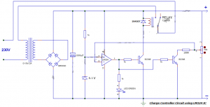
Battery Charge Controller Circuit by LM324 Comparator IC

Battery Charge controller

Battery Charge Controller Circuit Diagram 

Components Required:

  • LM324 IC
  • Zener diode 5.1V
  • Bridge IC/1N4007X4
  • Diode 1N4007
  • Transistor BC548X2
  • Led Green
  • Capacitor 1000uF
  • Resistor 1KX4, 100K
  • Pot 50K/47K
  • Relay 12V/10A
  • Transformer 0-15V/2A

LM324 Pinout Diagram


LM324 pinout diagram

LM324 Pin Description


Pin#Pin NamePin Description
1Output 1The output of IC’s First Operational Amplifier
2Input1(-) / Inverting Input 1Inverting Input of IC’s First Operational Amplifier
3Input1(+) / Non Inverting Input 1Non-Inverting Input of IC’s First Operational Amplifier
4Vcc / Positive SupplyPositive Supply of IC / Positive Supply of
All Operational Amplifiers.
5Input1(-) / Inverting Input 2Inverting Input of IC’s Second Operational Amplifier
6Input1(+) / Non Inverting Input 2Non-Inverting Input of IC’s Second Operational Amplifier
7Output 2The output of IC’s Second Operational Amplifier
8Input1(-) / Inverting Input 3Inverting Input of IC’s Third Operational Amplifier
9Input1(+) / Non Inverting Input 3Non-Inverting Input of IC’s Third Operational Amplifier
10Output 3The output of IC’s Third Operational Amplifier
11Ground (GND)Ground / Negative Supply of IC / Negative Supply of
All Operational Amplifiers.
12Input1(-) / Inverting Input 4Inverting Input of IC’s Forth Operational Amplifier
13Input1(+) / Non Inverting Input 4Non-Inverting Input of IC’s Forth Operational Amplifier
14Output 4The output of IC’s Forth Operational Amplifier

LM324 IC Features| LM324 IC Technical Specifications

  • LM324 IC has Four high gain operational amplifiers in a single package.
  • The DC gain of each op-amp is 100dB.
  • All four op-amps can be operated from a single supply.
  • It is Operated from a wide supply voltage from 3V to 32V.
  • It has Input and output are protected from overload.
  • It can take on a very low operating current drain 700uA to 800uA
  • The maximum bandwidth is 1MHz.
  • The IC can be easily used with logic devices and microcontrollers.
  • Having internally short circuit protected.

Applications of LM324 IC Comparator

  • Used in Sensor Circuits
  • Used in Small Signal Amplification
  • Widely used in General Operational Amplifiers Circuits
  • used for Audio preamplifiers
  • Filters
  • And also used in Comparator Applications

LM324 IC Datasheet Download

Here you can download the datasheet of the LM324 IC link given below I just copy and paste a link

https://pdf1.alldatasheet.com/datasheet-pdf/view/212589/NSC/LM324.html

October 26, 2021

What is a Filter Capacitor? | Filter Capacitor Working and Applications

The Filter Capacitor is the basic type of capacitor there is no difference from the other capacitors, it depends on the type of working. The capacitor is a reactive component used in analog electronic filters due to the function of the capacitor’s impedance frequency. Depending on the frequency of the capacitor that affects the signal. This property is therefore widely used in the design of filters. Analog electronic filters such as LPF can be used to perform a predefined signal processing function.

Capacitor Images

Filter Capacitor

The main function of this filter is to allow low frequencies and avoid high frequencies. Likewise, HPF allows high frequencies and inhibits low frequencies. An electronic filter can be made using analog components such as resistors, capacitors, transistors, operational amplifiers, and inductors. This article provides an overview of the filter capacitor and how it works.

Read Also: What is a Coupling Capacitor | Applications of Coupling Capacitor

What is a Filter Capacitor?

The capacitor used to filter a specific frequency is called a filter capacitor, which is a series of frequencies in the electronic circuit. Typically, a capacitor filters low-frequency signals. The frequency value of these signals is close to 0 Hz, also called DC signals. This capacitor is therefore used to filter out unwanted frequencies. They are very common in a wide variety of devices such as electronics and electricity and are applicable in a variety of applications.

Filter Capacitor Working

This capacitor works on the principle of capacitive reactance. Capacitive reactance means that the impedance value of a particular capacitor varies depending on the frequency signals flowing through the respective capacitor. Take the example of a resistor in a circuit. The resistance of the device does not change, it provides the same resistance depending on its constant value. But a capacitor has a variable capacity. The capacitance is affected due to the applied frequency value of the signals.

The work of this capacitor is mainly based on the principle of capacitive reactance. The impedance of a capacitor is nothing more than how it changes with the frequency of the signal passing through it. A non-reactive component such as a resistor provides resistance equal to the signal rather than the frequency of the signal. This means that the 1Hz and 100KHZ signals pass through the resistor with equal resistance.

But, impedance or resistance is different from a capacitor, it will change based on the signal frequency which is flowing through in it. They are reactive devices that provide high resistance to low-frequency signals and low resistance to high-frequency signals using a formula such as XC = 1 / 2πfc. A capacitor gives unequal impedance values for an unbalanced frequency signal. In the circuit, it can act as a resistor.

Read Also: Types of Diodes | Applications of Diodes | Rectifier, Clipper, Reverse Current Protection

Filter Capacitor Formula

The filter Capacitor is widely used in power supply circuits, which is for reducing ripple at the output.

The formula is C = I / 2f Vpp

the above formula I is the load current, f is the input frequency and Vpp is the minimum ripple that may be acceptable.

= 1/2* 3.14* f c

where Xc is the capacitive reactance.

Capacitor Symbol

Capcitor Symbol

Capacitor Symbol

Filter Capacitor Circuit To Block DC and Pass AC

It has already been discussed that it offers low resistance compared to high-frequency signals and high resistance compared to low-frequency signals. To avoid the direct current DC, we must give priority to high-frequency signal transmission. In this case, the designed circuit acts as a high pass filter.

Filter capacitor Circuit

Filter Capacitor Circuit Diagram

Several times in a circuit, the DC and AC signals must be used at at least one stage of the circuit. However, in another step, in the circuit, we may only want to pick up AC and DC signals. A microphone circuit is one example. We need DC power as input to turn ON the microphone and we need AC power as input, which indicates the voice signal or music that the microphone wants to record.

Filter Capacitor Applications

Applications of filter capacitors are,

  • Filter Capacitors can be used for the design of high pass filters, low pass filters, etc…
  • The capacitor can be connected after the voltage regulator to reduce ripple in the DC power supply.
  • capacitor most widely used in audio, IF, or RF filters.
  • It is preferred in the processing of signals.
  • These capacitors are used for glitch removal on DC power rails.
  • protective circuits where the concern is about heavy loads such as air conditioners and refrigerators.

October 18, 2021

Types of Diodes | Applications of Diodes | Rectifier, Clipper, Reverse Current Protection

What is a Diode?

In this article, we discuss what is Diode and its Applications of Diodes and where we can use it. A diode is an electronic component that can be used to control the flow of electricity. It has two terminals, an anode, and a cathode. The purpose of the diode is to allow current to flow in one direction but not the other. The components that make up a diode are the anode, cationic, cathode, and passivated film.

When electricity flows through a diode, current flows in only one direction: from positive (+) to negative (–). This is why a diode is commonly symbolized by a line with an arrow through it. The arrow symbolizes the current that flows in only one direction. The line symbolizes that the current is traveling in one direction only.
 

Applications of Diode

Diode Symbol

Generally, the diode is made with semiconductor materials like P and N namely Anode and Cathode are the two terminals. The diode having Forward bias and Reverse bias depends on the type of voltage applied which is positive and negative.

Forward Bias: When the applied voltage to the anode is positive with respect to the cathode and the diode is in Forwarding Bias. The diode will conduct when the voltage applied to the diode is greater than the threshold level generally says o.6v for silicon diodes and 0.7V for germanium Diodes. In this condition, the diode will act as a short circuit and allow the current to flow through the diode.

Reverse Bias: When the Voltage applied to the cathode is positive with respect to the anode, then the diode said to be in reverse bias is done by the polarity of the diode is changed. In this condition, the diode will act as an open circuit, and it doesn’t allow the current to flow through the diode.

Types of Diodes

Various types of diodes available in the market you can choose depend on the electronic design, here various types of diodes used depend upon the different types of applications. they are,

P-N Junction Diode

Rectifier Diode

Schottky Diode

Light Emitting Diode

Photo Diode

Laser Diode

Zener Diode

Tunnel Diode

Silicon Controlled Rectifier

Vacuum Diode

Applications of Diodes

Diodes are used in a wide variety of applications to control the flow of electricity. In the simplest sense, diodes can be used to prevent current from flowing in one direction, while allowing current to flow in the opposite direction. This is how diodes are used in battery backup systems to prevent electricity from flowing to your home when the power is off. Diodes can also be used to detect when current is flowing, such as with burglar alarms and motion detectors.

As per Applications of Diodes can be Achieved by the following circuits,

  • Rectifiers
  • Clipper Circuits
  • Clamping Circuits
  • Reverse Current Protection Circuits
  • In Logic Gates
  • Voltage Multipliers

Rectifier

Generally, the Diode is used for the rectification of AC power into DC power, using these diodes we can build different types of rectifier circuits. The most common type of rectifier circuits are Fullwave, half-wave, Center tapped, and full-bridge rectifier circuits. You can find below the diode operation as a rectifier.

Halfwave Rectifier

halfwave rectifier

Halfwave Rectifier

From the above waveform during the positive cycle the input is given to the anode of the diode with the respective cathode, so the diode is forward biased already discussed above and in that case current flowing to the load. The voltage across the load is the same as the supply voltage.

During the negative half-cycle of the input given to the anode of the diode with respect to the cathode, there is no current flowing to the load, this is reversely biased in that case, there is no current flowing to the load. This is an open circuit and no voltage shows across the load. Both voltage and current at the load side are of one polarity means the output voltage is pulsating DC. If you want to get continuous DC without any ripples you should use a capacitor that is connected across the load.

Clipper Circuits

Clipping Circuits consist of a diode and resistor. These circuits are widely used in FM transmitters, where the excessive noise peaks are removed by using these clipper circuits.

Clippers may be classified into two types based on the placement of the diode.

  • Series Clippers
  • Shunt Clippers

Series Clippers

Series clipper

The above figure shows the positive series clipper circuit the diode connected to input in reverse bias the positive half cycle clipped in output voltage waveform. In the positive series, clipper output kept zero due to the diode connected in reverse bias, during the positive half-cycle.

Hence, the positive half cycle of the out waveform was removed. during the negative half-cycle, the diode conducts because the diode is in a forward direction the voltage appears in the output waveform.

Shunt Clippers

positive shunt clipper

In a positive shunt clipper circuit, the diode is shunted across the output, from the above circuit during the positive half cycle the diode is forward biased so the output voltage gets zero due to the diode acting as a closed switch.

During the negative half cycle, the diode is reverse biased and acts as an open switch so the output will appear in the waveform. the above both series and shunt clipper positive half cycle is clipped in the output waveform.

Clamping Circuits

What is a Clamper? Clamping Circuit provides an important role in output waveform and is used to shift either the positive or negative peaks of the input signals to a required level. This clamping circuit can be used as negative or positive which depends on the diode configuration. this circuit is also called a level shifter or DC restorer.

Here clamper circuits classified into two types they are,

  • Positive Clamper circuit
  • Negative clamper Circuit

Positive Clamper Circuit

positive clamper circuit

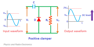
Positive Clamping Circuit that changes the DC level of a signal to the desired level without changing the shape of the applied signal. If the circuit pushes the signal upwards then the circuit is called a positive clamper. When the signal is pushed upwards, the negative peak of the signal gets the zero level.

Negative Clamper Circuit

negative clamper Circuit

A negative Clamping Circuit opposite of a positive clamper, if the circuit pushes the signal downwards then the circuit is said to be a negative clamper. When the signal is pushed downwards, the positive peak of the signal meets the zero level.

These clamping circuits can be positive or negative depending on the diode configuration

Also Read: What is Clamper Circuit?


October 15, 2021

Variable Resistor Symbol | Rheostat Symbol & Types of Variable Resistors and Applications

What is a Variable resistor:

A Variable resistor is a type of resistor in which the electric flow of current can be controlled by adjusting the resistance value. This variable resistor works the same as a normal resistor at a fixed value and if the resistance value increases in the variable resistor the current through the circuit decreases and if the resistance value decreases the current flow through the variable resistor increases. It is also used as voltage-controlled across devices in a circuit. The variable resistor must operate by sliding the contact (wiper) onto the electromechanical transducer and usually on the resistive element.

Variable Resistor Symbol:

variable resistor symbol


Types of variable resistors:

Potentiometer:

The potentiometer is a type of resistor and is a three-terminal resistor with a rotating contact. It functions as a potential divider If only two terminals are used, one end and the wiper, it acts as a variable resistor or rheostat. The principle of a potentiometer is that the potential dropped across a segment of a wire of uniform cross-section carrying a constant current is directly proportional to its length.

Potentiometer symbol

Resistor:

A resistor is an electrical component that resists the flow of electric current. It is used to control the amount of current flowing in a circuit, as well as to adjust the voltage level in a circuit. Resistors are typically made from materials such as carbon or metal, and their resistance is measured in ohms. They are widely used in electronic circuits to perform a variety of functions, including voltage division, current limiting, and power dissipation. They come in various types and shapes, such as fixed resistors, variable resistors, wire-wound resistors, and surface-mount resistors. The most common type is the carbon composition resistor, which is a simple and inexpensive option.

Applications of Potentiometers:

Potentiometers are commonly used to control electrical devices

  1. Volume controls in Audio Circuits.
  2. Potentiometers can be used as position mechanism transducers.
  3. Potentiometers are used in Joysticks.
  4. Variable Resistors are measurements of the distance or angles, tuning of the circuits, and many more.
  5. Potentiometers are used as amplifier gain control.
  6. The potentiometer is used as a voltage divider in the electronic circuit.
  7. The potentiometer is used in medical equipment.
  8. The potentiometer is used in radio and television (TV) receivers for volume control.

Potentiometer Symbol:

potentiometer Symbol circuits99

Rheostat:

A Rheostat is a type of resistor the most common way to vary the resistance in a circuit continuously is to use a rheostat. The adjustable resistor is used in applications that require the adjustment of current or the varying resistance in an electric circuit. Rheostats are much related to the potentiometers in terms of construction, but they are not used as a potential divider, instead, they are used as variable resistors. The resistive wire is wound around an insulating ceramic core and the wiper slides over the windings

Rheostat circuit

Rheostat Applications:

  1. Rheostats are used in dim lights to change the intensity of light.
  2. It is basically used to adjust the magnitude of current in a circuit by changing length.
  3. Rheostats are used as the power controlling devices, which were connected in series with the load.
  4. Used in high-efficiency switching electronics.
  5. which are used in circuits to perform tuning or calibration.

Rheostat Symbol:

Rheostat Symbol


Variable Resistor Applications:

Variable resistors are widely used in a variety of electronic applications, including:

  1. Volume controls in audio equipment: Variable resistors are used to adjust the volume of music or speech.
  2. Light dimmers: Variable resistors are used to control the brightness of lights in homes and buildings.
  3. Motor speed control: Variable resistors are used to adjust the speed of electric motors in appliances and machinery.
  4. Temperature control: Variable resistors are used to control the temperature in heating and cooling systems.
  5. Potentiometers: Variable resistors are also used as potentiometers, which are devices that measure the electrical potential (voltage) in a circuit.
  6. Sensors: Variable resistors are used as sensors for measuring position, pressure, and other variables.
  7. Power control: Variable resistors are also used in power control circuits to adjust the amount of power delivered to a load.
  8. Filtering: Variable resistors are also used in filtering circuits to adjust the cutoff frequency of a filter.