

PWM LED Lamp Dimmer Circuit
PWM LED Lamp Dimmer Circuit NE555 Timer IC is discussed in this article on www.circuits99.com. PWM based dimmers which can hit well over 90% efficiency. Since less amount of power is wasted as heat, the switching elements of PWM dimmers require a smaller heatsink and this saves a lot of size and weight.
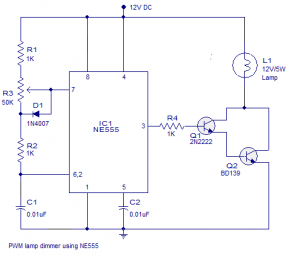
PWM LED Lamp Dimmer Circuit NE555 Timer IC
NE555 timer IC which is wired as an astable multivibrator operating at 2.8KHz forms the heart of this PWM LED Lamp Dimmer Circuit NE555 Timer IC. Resistors R1, R2, POT R3 and capacitor C1 are the timing components. The duty cycle of the NE555 Timer IC’s output can be adjusted using the POT R3. NE555 Timer IC higher the duty cycle means higher the lamp brightness and lower the duty cycle means lower the lamp brightness.
In PWM LED Lamp Dimmer Circuit Diode D1 by-passes the lower half of the POT R3 during the charging cycle of the astable multivibrator. This is done in order to keep the output frequency constant irrespective of the duty cycle. Transistors Q1 and Q2 form a Darlington driver stage for the 12V lamp. Resistor R4 limits the base current of transistor Q1.
Tags:
555 timer pin diagram
555 timer circuit diagram
555 timer working
555 timer monostable
555 timer applications
555 timer pdf
555 timer internal circuit
ic 555 block diagram