
Rain Alarm Circuit Diagram
The Simple Rain Alarm Circuit Diagram is used to give an alert when it’s going to rain. This circuit is used in homes to guard their washed clothes and other things that are vulnerable to rain when they stay in the home most of the time for their work. The required components to build this circuit are probes. 10K and 330K resistors, BC548 and BC 558 transistors, 3V battery, 01mf capacitor, and speaker.
Circuit Diagram
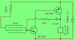
Simple Rain Alarm Circuit Diagram
Whenever the rainwater comes in contact with the probe in the above circuit, then the current flow through the circuit to enable the Q1 (NPN) transistor and also Q1 transistor makes Q2 transistor (PNP) to become active. Thus the Q2 transistor conducts and then the flow of current through the speaker generates a buzzer sound. Until the probe is in touch with the water, this procedure replicates again and again. The Simple Rain Alarm oscillation circuit built in the above circuit that changes the frequency of the tone, and thus tone can be changed.
Nice articles