
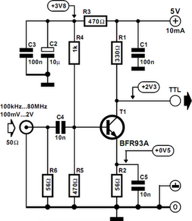
Sine Wave To TTL Converter Circuit Diagram
Sine Wave To TTL Converter is a series that we can use to change the sine wave signal with a pulse shape with the same frequency with TTL logic level that we are ready to use in coding the data digitally. The series of Sine Wave To TTL Converter can be used to convert sine wave signal to form a TTL of frequency 100KHz to 80MHz at the level of 100mV – 2V. The series of Sine Wave To TTL Converter uses a 5VDC voltage source.

Sine Wave To TTL Converter circuit
The series of Sine Wave To TTL Converter was built from transistor T1 gets base bias from R3, R4, and R5. If the series Sine Wave Converter This TTL To get the input sine signal with a minimum level of 100mV, the circuit Sine Wave To TTL Converter This will generate an output signal with TTL level square wave